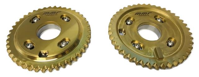
MMR adjustable cam gears allow adjustment of your camshaft timing. The 2V SOHC & 4V DOHC engines have the ability to make horsepower, but the factory timing settings can limit this. MMR Adjustable cam gear sets provide up to 12 degrees of camshaft advance or retard.
They fit all factory and aftermarket camshafts and installs just like the original factory gears. The sets feature both a steel inner and outer gear for increased durability and performance.
MMR’s design uses a center bolt AND outer bolts to hold adjustments firmly in place, no more relying on just the outer bolts to hold the turning forces making these gears the best available.
Features:
- Billet Steel Construction
- Inner and Outer Bolts secures adjustment
- Stainless Steel Outer hardware prevents false trigger signal
- Titanium Nitride Coating reduces wear
- Adjustment window with laser etched marking assists with adjustment
Cam Gear Installation Notice
Ford used two different engine assembly plants, which incorporated two different camshaft configurations for the 2V Modular Engines. Before installing the adjustable camshaft gears, it is very important to check the original factory camshafts to determine which plant your engine came from. All of the Romeo Engine Plant engines (used in most ‘99 and up car applications, all car engines before ‘99 & all Modular engines before ‘96) used camshafts with separate, bolt-on cam gears and spacers (OEM Part #s: Gear RH = F8AE-6256-AA, Gear LH = F8AE-6256-BA, Spacer = F3AZ6265-A (2 spacers total, 1 on each side). These parts can easily be taken off the factory cams and reused on the adjustable cam gears.
All of the Windsor Engine Plant engines (Most truck engines after 1996 and some Mustangs after ’98) came with gears that are permanently pressed onto the factory camshafts and cannot be removed. These Windsor plant engines ALWAYS require the use of one OEM part #F3AZ-6265-A spacer behind each of the adjustable cam gears (2 spacers total, 1 on each side).
Camshaft Gear Installation
Please ensure that you have received all necessary components before beginning installation. NOTE: All torque specs are for dry bolts.
Step-by-step instructions for the timing sprocket removal and installation procedure can be found in the factory FORD service manual.
1. Begin by removing the necessary components from the front of the engine in order to gain access to the Engine Front Cover.
2. Remove the necessary components to gain access to and remove the Valve Covers.
3. Position the crankshaft with the keyway at the 12 o’clock position.
4. Remove the timing chain tensioner bolts from both timing chains
- Remove the bolts.
- Remove the timing chain tensioners.
- Remove the timing chain tensioner arms.
5. Remove the Left-Hand (LH) and the Right-Hand (RH) timing chains and the crankshaft sprocket.
- Remove the RH timing chain from the camshaft sprocket.
- Remove the RH timing chain from the crankshaft sprocket.
- Remove the LH timing chain from the camshaft sprocket.
- Remove the LH timing chain from the crankshaft sprocket.
6. Most factory timing chains have either a lighter or darker link than the rest of the chain on either end to use as a timing mark. If the 2 off-color links are not visible, follow the instructions below
- Stretch each chain until the loop forms two parallel lines.
- Clean the face of each link at both ends of the line.
- Mark the cleaned links with a paint pen to use as timing marks
8. Take the MMR adjustable cam sprockets and slightly loosen the 4 retaining bolts on the face of each sprocket.
9. Place the new sprockets on camshafts. A adjustable cam gears have been etched to identify the correct installation location: left (driver) and right (passenger).
- The left cam gear is placed on the driver side exhaust camshaft of 4-valve engines and on the driver side camshaft of 2-valve engines.
- The right cam gear is placed on the passenger side exhaust camshaft of 4-valve engines and on the passenger side camshaft of 2-valve engines.
10. Once the new camshaft gears are placed on the camshafts, ensure that the internal timing mark is pointing at 0°.
- Rotate the right camshaft gear until the outer timing dot is approximately at 11 o’clock.
- Rotate the left camshaft gear until the outer timing dot is approximately at 12 o’clock.
11. Ensure that the crankshaft is in position so that the number one cylinder is at top dead center (TDC).
12. Install the timing chain guides. Torque the bolts to 89 lb-in.
13. Position the driver side timing chain on the crankshaft sprocket. Align the center of the marked link, with the mark on the crankshaft sprocket.
14. Install the other end of the driver side timing chain on the left camshaft gear. Align the center of the marked link, with the timing mark on the new gear.
15. Position and install the driver side timing chain tensioner assembly. Torque the bolts to 18 lb-ft.
16. Position the passenger side timing chain on the crankshaft sprocket. Align the center of the marked link with the timing mark on the crankshaft sprocket.
17. Install the other end of the passenger side timing chain on the right adjustable camshaft gear. Align the center of the marked link with the timing mark on the new camshaft gear.
18. Position and install the passenger side timing chain tensioner assembly. Torque the bolts to 18 lb-ft.
TIMING ADJUSTMENT
REMINDER BEFORE PROCEDING: It is extremely important to adjust BOTH camshafts when setting the mechanical timing. If you adjust the left camshaft to 4° advanced, the right camshaft must also be adjusted to 4° advanced. Failure to do so may result in severe engine damage.
1. If the valve springs are still installed, the camshaft may have rotated due to spring load, and depending on how loose the cam sprocket bolts are, may have moved the cam gears to full advance or retard. To adjust cam timing, follow the procedure below:
- Slightly loosen the (4) M6 retaining bolts around the center of the cam sprocket.
- Slightly loosen the M12 bolt at the center of the cam sprocket.
- Rotate the adjustable camshaft gear counterclockwise to advance the camshaft timing or clockwise to retard the camshaft timing. Use the pointer in the timing window to line up with the desired timing mark.
- While holding the camshaft gear in position, temporarily tighten the center bolt enough to prevent the sprocket from rotating against the spring pressure.
NOTE: MMR strongly recommends that you degree the left and right camshafts in order to verify that the chains are installed correctly before proceeding.
- One at a time, torque each M6 bolt to 120 in-lbs with red Loctite.
- Once all 4 M6 bolts have been torqued with Loctite, torque the center bolt in 2 steps:
- i. Tighten the bolt to 30 lb-ft.
- ii. Tighten the bolt an additional 90°, or a ¼ turn.
NOTE: You should always check piston to valve clearance when using an adjustable timing set before attempting to start the engine after adjustable cam sprocket installation.
2. Once all bolts have been torqued, the engine front cover, valve covers, and any additional components that were removed to provide access for cam sprocket installation may be reinstalled.
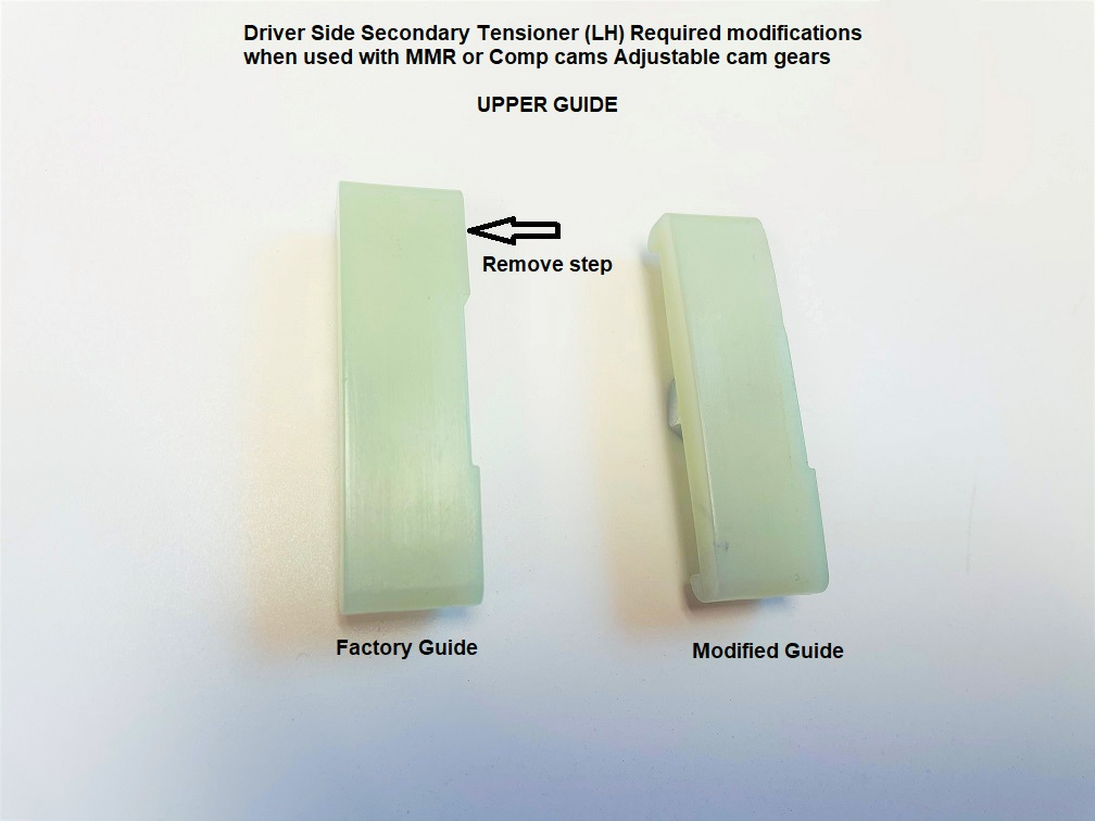
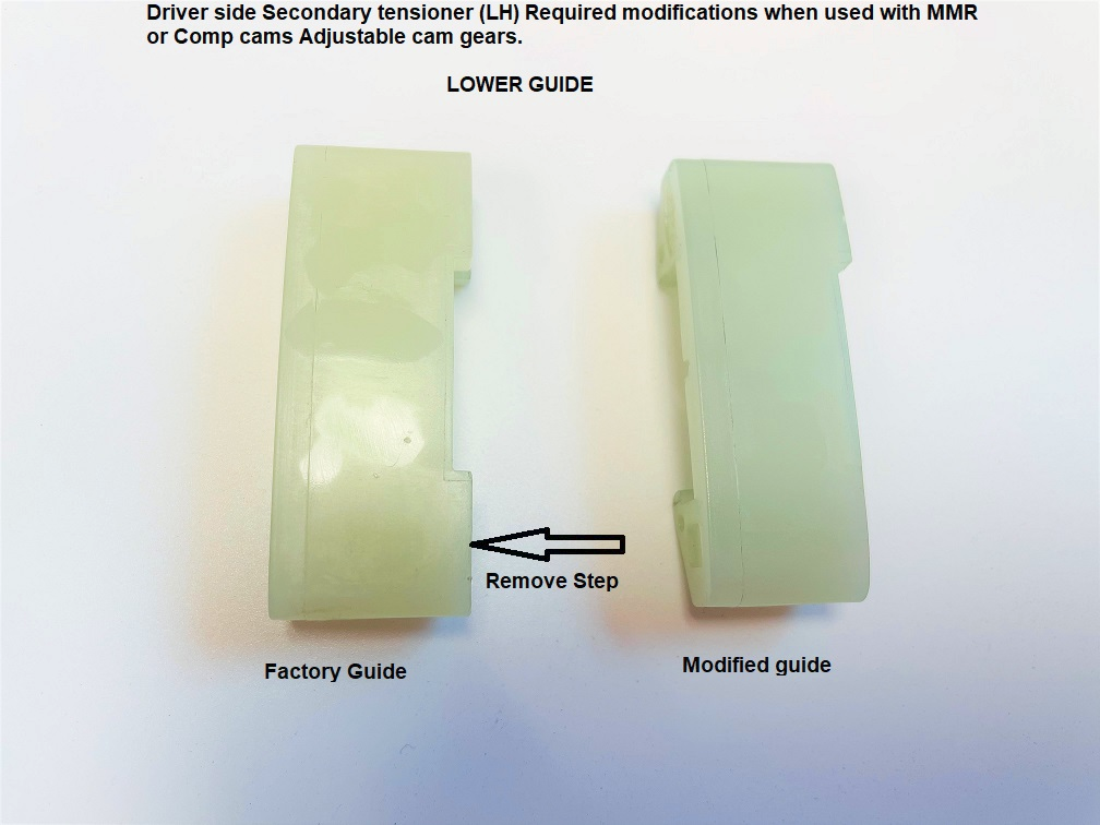
When using the MMR adjustable gears with MMR billet secondary drivers side tensioner, the following modifications must be made: